Power cord Hole

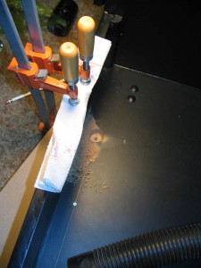 The first order of business was putting in the monitor. Looking back on thing putting in the monitor should have been one of the later things, but…oh well. Live and learn. I realized early on that I forgot to drill a hole for my power cord. Doh’. So, Being very careful not to goof up all the paint, I strapped a board to the bottom of the cab and drilled my power cord hole. This was a painless procedure. Also, I ran the vacuum tube through the coin door hole. Anytime I had to drill, I would turn it on so all dust was immediately sucked up (except for the power cord hole). Then I put in the smart strip.
Aux Power Supply
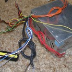
I decided that I wanted car speakers and amp for a little stronger audio source. I also wanted to use cold cathode lighting. I did not want to run either off the computer PS, so I installed an auxiliary PS. Seeing as I would not be hooking this up to a computer, I did away with the Molex adapters,then trimmed and sorted the wires. I capped each line with heat shrink that I was not using.
This way the feeds would be there if I wanted them for future add-ons, but 1. Would not be a safety concern in the mean time and 2. Would be neater wiring in the cab. You will notice that the 2 lead sets that ware coming off to go to the amp and the lighting also have a green and black pair. I soldered these together and heat shrank it to the bundle. This way the PS is always on as long as there is power. I shortened the 2 PS power cords to about 1 foot.
Securing the PS’s
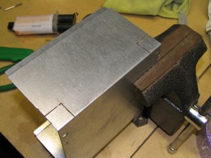
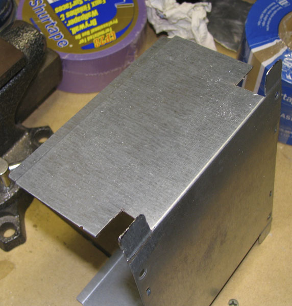
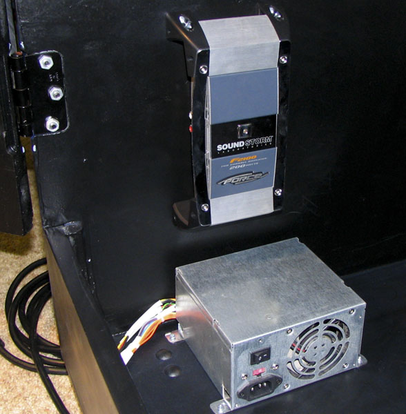
I did not want to make a custom bracket for the 2 power supplies. So, I took the PS apart and used the bottom to be my connector. I used a Dremel to cut tags on the PS. I bent them out flat and pre drilled holes in them. Then after I drilled pilot holes on the cab I attached the PS. Rock solid!!! I then attached the amp to the right side of the cabinet (inside left).
Coin Door
In the evenings my kid likes to play outside. Duh, it is summer and kids play outside when it is nice out. So, I used that time to work on out door cab projects. I think I mentioned it before, but I got a over under coin door at a not so near by pinball dealer. When I went to get my back glass for my Black Knight, I was a sawed off dynamo being as a TV stand. I asked if he would sell the coin door out of it. He said I could have it for $15 if I pulled it myself. SOLD!
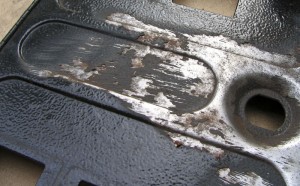
I do not know where this thing had been but if was covered in crap. The coin mechs had to be dremmiled clean with the soft wire brush. This stuff was stuck on. The mech holders had some mystery goop on it. I became almost OCD about cleaning my hands after dealing with it. I feared that I was handling someone’s puke or worse. But hey 15 bucks is 15 bucks eh’.
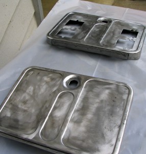
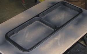
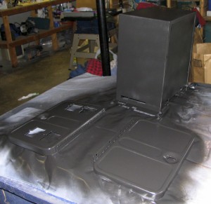
I wound up taking the entire thing apart. I took a stiff wire wheel doors and frame. Afterwards I sanded everything nice and clean. I opted for the Rust-o-lium Satin instead of the original hammered look. It came out really slick.
Motherboard
I had a computer that I had set aside for the project. When I went to set it all up the computer decided it would rather kill it’s self, instead being involved with this project. I was really bummed. My partner in arcade crime, Neal, had a Celery 1.8 GHZ that he was not using that he donated to the cause. Woo hoo! Nice case too, but the computer was destined to be inside the cab caseless.
When removing the mother board I took lots of pictures so I would remember where to put everything. I have to tell you, having a camera on my phone is a wonderful tool in situations where I forgot my real camera. I also made a map of the screw holes so I would not forget any. 12 screws. I was not sure if I needed all of them, but it would seem that is I was adding or removing IDE lines or power or video cards, not having all the support might damage the board, so I decided to do all 12. The motherboard would not sit flat against the wall so I found some 1/4 in nylon stand offs at the Home Depot. I will just say for the record that mounting a motherboard to the side of a cabinet, maintaining level, and getting little stand offs on with the screw in it while balancing between the monitor and the floor of the cab was a major main in the posterior. Remember the comment about perhaps putting the monitor in later? So, I screwed one screw (with stand off) in the center top hole of the motherboard. I leaned in the cab on one elbow (left) got the stand off in a pair of pliers in my right hand. I put the level on top of the motherboard, found maintained level with the left hand, put the stand off behind the motherboard with the right, then pushed down on it with the right while grabbing the screwdriver with the left, fidgeting to get a screw and placing it through the hole and finally tightening it down (which was the easiest part). Needless to say, I did not take a picture of this process.

Hard Drive Mounting
While I was taking the PC apart, that there was all sorts of usable metal bits in the case. I decided to use this stuff for many parts of my cab. I dremeled off the hard drive cage (it was tack welded in there) and modified it to be screwable to the cab. I put some holes in it, bent it, painted it, put it in the cabinet, added the hard drives, and screwed them in. I did the same for the DVDr Drive. When I got the DVDr installed, I realized that the lip of the door stop was right in front of the DVDr. I decided to try to open the tray. To my relief, tray misses the door stop lip by about 2 or 3 mm. Whew.
 |
 |
Menacing Little Blue Light
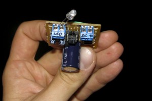
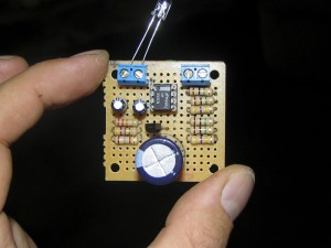
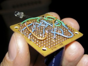
I have always liked how Macs have the power light that slowly just fades on and off. I decided that my cab needed a similar thing. I pulled out the ol’ RadioShack project books and started looking for a schematic. I did not find exactly what I was looking for so I set out to create my own recipe. After experimenting for a while, I finally had a good balance in fade timing. I dug through my old electronics stuff and pulled out piece of perf board and began constructing. About 3 hours later I had a working pulser. I put the circuit near the coin door as my main power button is mounted near by here too. I ran the little wall wart PS to the outlet on the smart strip that is always hot.
I love it, it sort of gently taunts you. Come here… Play me…

The On buttons switch was then wired to the motherboard power on connection. I used the connector that was originally attached to the motherboard switch as it had the header receptacle already on the wires. I soldered on an extension and attached it to the button. It was easy and it works great.
Control Panel Wiring.
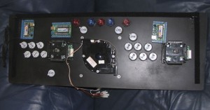
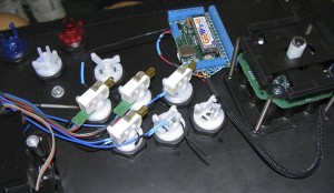
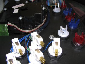
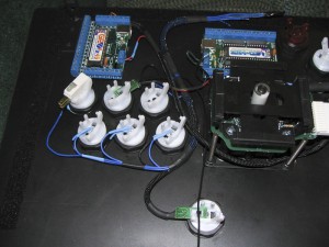
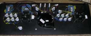
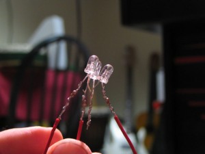
This seems to be one of the most time consuming parts of the entire build. I had 32 channels of LED lighting, 2 – 49 way Joysticks, 21 buttons, , a track ball, track ball buttons, USB for all the interfaces, plus a custom lighting wiring adapter that would feed the rest of the cabinet (coin door switches, LEDS…). I started with the LED wiring. 5 buttons will be using RGB LEDs while the rest will use Blues except for 3 reds at the top. After all the Push Buttons, Joys, TB, +Interfaces were in, I realized that there was a significant shortage of real estate available for clean wiring. But I set out to do just that. I decided to use wire looms I bought from Frys. I bought a roll of 1/4 in and got a package that contained a variety of different sizes. Every time there was any distance between source and destination, I would loom it. This way all wires would be both secure and tightly bound together. I did the player 1 LEDs first. I tested each LED Before and after I added them because I did not want to get to the end of all the looming, heat shrinking, and soldering to find out that I had a problem somewhere. I build a little LED tester a few years ago which helped. I put heat shrinking at every solder point so there would be no shorts at some point in case something shifted. I decided to put all the resisters by the LEDWiz so I had only clean wire in the tight spaces. This seemed like a good idea, but as I soon learned, it also got very tight around the LEDWiz.
The RGB LEDs were set up with RG&B wires for easy tracing. I did all the LED and PushButton wiring in my living room while watching TV at nights. I have to say my family was very supportive in this trying time. (I sort of made a big mess). Little snippets of red, yellow, blue, green, black, and yellow wires everywhere. After Player 1, I did players 2 then the utility buttons (coin up, P1, P2, Esc, and Pause). This took several nights and mornings (before work).
Then I moved onto the push button wiring. After the LEDs, the PBs (Push Buttons) were a piece of cake. All the PBs were wired with yellow wire so they totally stand apart from the LED lines.
I talked to Randy T from Groovy Game Gear and asked if he saw any problem with me making the mouse buttons also connect to the GPWiz49s shift key. He did not see a problem. So, once in MAME, being that I would not be using the mouse buttons, the shift keys come into play. Buttons 1-5 on both P1 and P2 can all be shifted. This is great for quickly changing volume without having to leave MAME.
By the way, if you are someone who does a lot of soldering and feel that helping hands do not really help as much as one could hope for should check out the Panavise sets. I got one on e-bay for like $15. They can be like $85 at a store. But you can clamp a circuit board or LED or anything up to 9 inches and rotate it in just about any position. It is a GREAT TOOL!!!

Track Ball
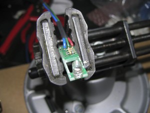
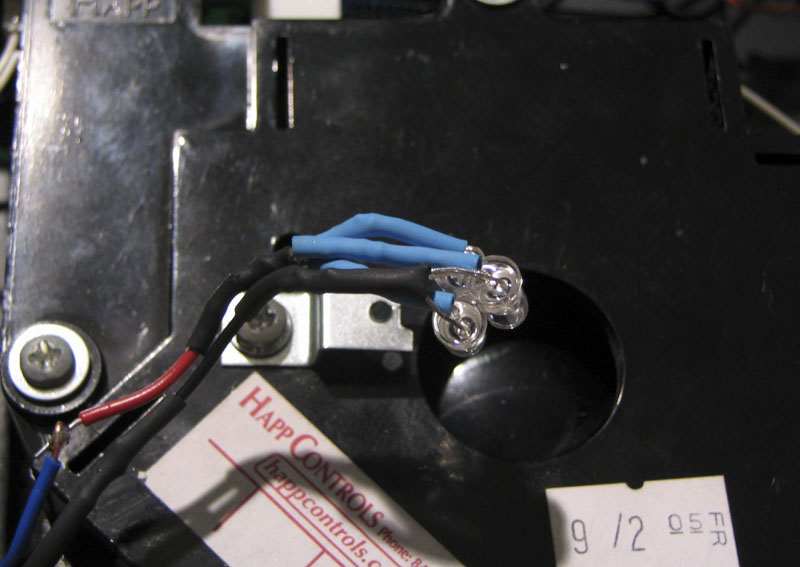
I hooked up the LEDs for the Track Ball. This was not a difficult thing. Wire, wire, snip, snip, solder, solder, heat gun, know, what I mean nudge, nudge, wink, wink, snap, click, know what I mean…He asked him knowingly.
Cable Tracks
I wanted the inside of the cabinet to be absolutely clean once it was finished, so, I installed cable tracks all the way around the bottom of the cab. I also have one track going up the left (inside right) front panel (coin door panel), and one track running up the back right inside of the cabinet (near the door) which takes all wires up to the speaker board area. All wires and cables travel through these tracks. There are no loose wires wandering aimlessly around the cabinet. This has helped during times when I would need to climb in there to work on stuff.

Speaker Board Wiring
I wired up the Speaker board via DB9 connectors. The connectors connect at the back of the cab for easy repairs (if needed). Also if I have to remove the monitor ever, the wiring needs to be disconnected in order to get the monitor frame out. The DB9 connector went to +12 and Ground (From Aux power supply), Speaker L & R, and lastly line 32 from the LEDWiz and a LEDWiz Ground. In each notch below the speaker holes, I placed a red LED. My speakers have a metallic silver grey color. This makes them light up really nicely. The cool thing is that they are not so bright that they are distracting, but just subtle. I like it. After everything was wired up, I put it in the cabinet. Wow, another piece in place and another step closer to being done.


LEDWiz
At this point I could no longer stand it. I had to fire it up and try out the LEDWiz. I played with it for several hours. I programmed many sets of animations and started to get the hang of it.

Marquee Light Board
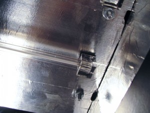
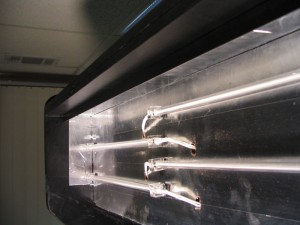
I used a piece of hard board for my light board. First I measured out where I wanted my hangers. I drilled out holes on the hardboard. I put the L brackets on and attached them through the hardboard. Then I put the hardboard in the monitor hole and marked where I needed to place my pilot holes (I had to take my speaker board down first). I drilled my pilot holes. On the hardboard I used Foil Tape to coat the surface. This way as much of the light as possible would go out the marquee, not get absorbed by the light board. I drilled wires for cold cathode to reach the inverters. May sound stupid, but I did not even want the inverters sucking up light, so I put them on the back of the light board with Velcro. I wired the inverters to the 12V feed and then the cold cathode tubes to the inverters. One thing to mention. I snipped the on off switches off of the inverters. I always wanted the marquee lights on if the cab was on. Plus I could not see unscrewing the entire sound board / light board set to turn off the Cold Cathode tubes.
The morning after I put the CCs on the marquee light board I noticed that the cheap POS foam tabs used to stick the CCs onto the light board with had fallen off in several places. I decided that this would not do, so I replaced all pads with the same heavy duty Velcro that I used for the CP top.
Marquee
I had used MAME Marquees for a few marquees in the past. Scott always did a bang up job. My only gripe is that when lit, the marquees look a little washed out. Plus you can see the paper texture through the print. Now, read this clearly, I am not saying that his products are bad. Actually, I feel quite the opposite about his stuff. I used him for my CP which I think totally ROCKS! I decided to go a little further for my Marquee. So I found a company (Megabytes Digital) which makes the translites for movie posters and restaurant menus. Actually they are the company that does all the translites for all the Chick Fil-A restaurants. This stuff is not printed on paper, but on a film type material using a milky substrate. Basically it is plastic, white on the back, color print on the front, and lit like film, so it is made to take light. So the colors are rich and very detailed when lit. I LOVE the way it turned out. It is thin, not like the old marquees, so it must be protected.
NOTE: As I understand it, MAME Marquees no longer uses just standard printing. It is apparently very similar to what I got from Megabytes.
Marquee Installation
I bought a piece of plexi for the Marquee. I cut two identical pieces so I could sandwich the marquee translite in between them. I made a holder out of 2 pieces of ¼ in. angled aluminum. First I put in the back piece so I could get it nice and straight. Then I put the 2 pieces of plexi against it and put up the second piece of aluminum and marked it. I wanted to get it as tight and close as possible. I set down the loose bits and predrilled the holes. I held up the plexi once more and screwed down the second piece of aluminum. It was a tight fit, but it was strong enough that everything held into place without the use of the marquee retainer.
 |
 |
At this point I had to make the leap and take the plastic off the plexi. I decided to try an experiment. When you work with electronics, sometimes you have to wear an anti static strap. This is to dissipate a static charge so you don’t fry sensitive components. I tried this in reverse. I strapped the marquee plexi to the strap then to me. My hope was that I would absorb the static charge generated by the plastic removal. I’m not sure if it really worked or not, but they were not covered with dust after I removed the plastic. I quickly placed the marquee down, put the plexi on top, trimmed the marquee, put the back plexi on and mounted it into the grove mentioned above.
I placed T-nuts across the top edge of the speaker board. These are for the marquee retainer. I got some hex screws and sprayed them black. I measured the retainer and cut it to length. I drilled the holes and installed it on the cab. I like the hex nuts as they give a little more authentic look to the retainer.


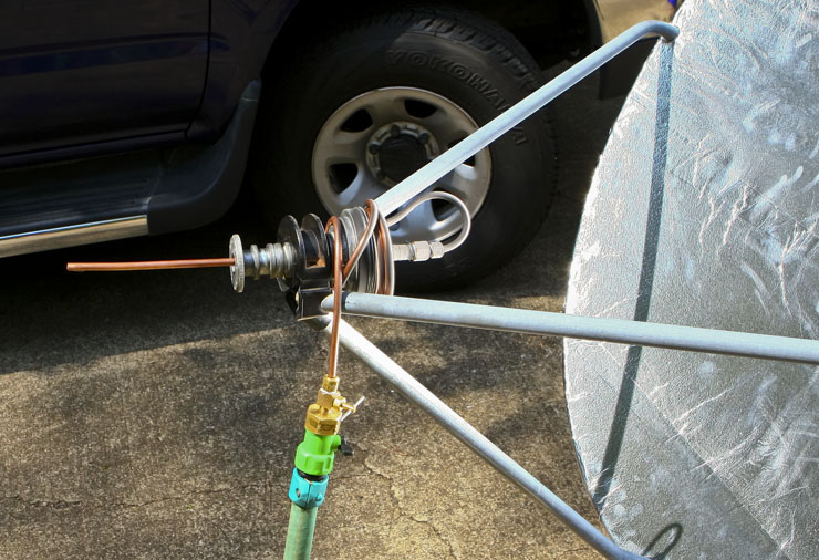
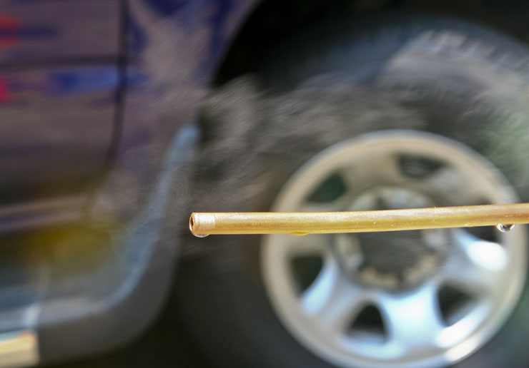
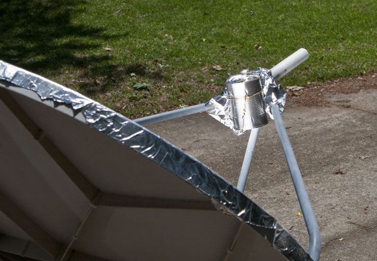
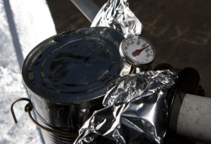
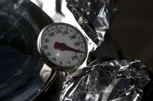
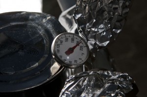
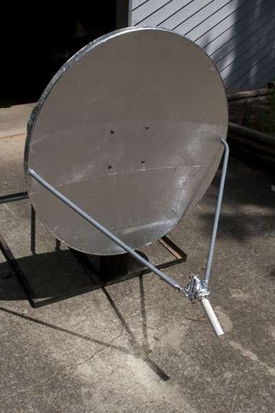
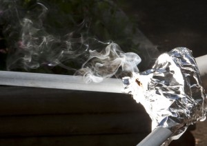
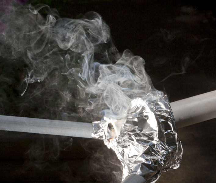
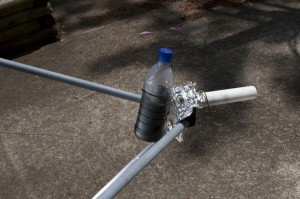
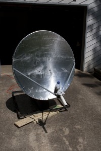
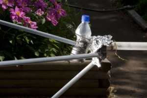
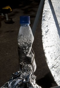
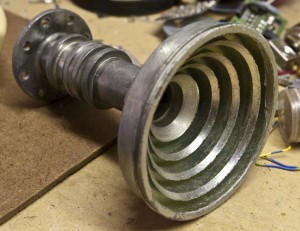 I wanted to see if I could get a solid stream of steam. If not steam, at least a good flow of hot water. Perhaps a insanely large tea maker. My hope was that if I could get steam, I can turn a small turbine. I looked again at the feed horn. I decided to pull off all the stuff that might melt. It was a actually a rather nice looking piece of machined aluminum. If I wasn’t so intent on making this solar thingmabob, I could see it being a very Star Wars candle holder or wine goblet. Since this piece fits perfectly into the holder (as it was sort of designed to be there), it will be used as the mount for my steam chamber. My thought is this, if I can get the water to flow slowly enough, and get a
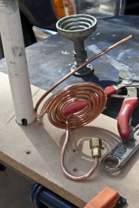
 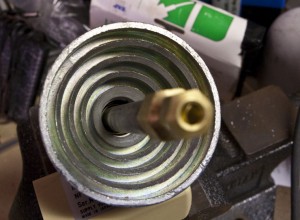 tube hot enough, once the water hits it, it will flash to steam. I bought some 1/4 in coper tubing, some brass fittiings and a 6 inch 1/2 in. diameter metal pipe. I made a coil with the brass tubing that flows in a spiral towards the center of cone on the horn. The idea being that the cool water starts on the outside and warms up as it moves towards the center. Then water is then directed up into the larger metal pipe. The pipe will is in the focal point, so it should be the hottest object on there. Man this is hard to write as nothing has a real name.



 The first order of business was putting in the monitor. Looking back on thing putting in the monitor should have been one of the later things, but…oh well. Live and learn. I realized early on that I forgot to drill a hole for my power cord. Doh’. So, Being very careful not to goof up all the paint, I strapped a board to the bottom of the cab and drilled my power cord hole. This was a painless procedure. Also, I ran the vacuum tube through the coin door hole. Anytime I had to drill, I would turn it on so all dust was immediately sucked up (except for the power cord hole). Then I put in the smart strip.

