 A few weeks ago I got a call that my grandfather passed away.
I gave up the build progress for a couple of weeks (for good reason).
Death puts a weird spin on everything. Actually I had no real interest in working on this thing at all when I got back. It has taken me about a week to force myself to get back into the swing of things (I have a tendency to let a project go cold if I do not keep up the momentum).
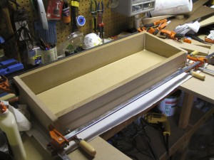
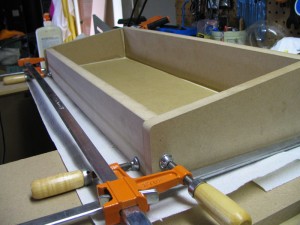
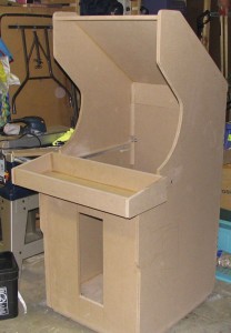
I started my CP. It is going to be 32 in wide and 12 in deep. I decided that I wanted to put t-molding on the rails, so I put the sides on the sides rather than on the centered inside of the front and rear boards. I wanted a slight slope towards the player. There is a 1 in drop from the back to the front. It is a comfortable angle.
 |
 |
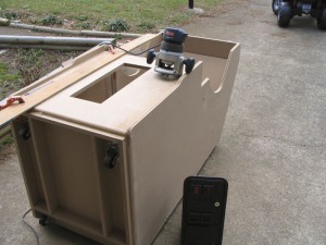
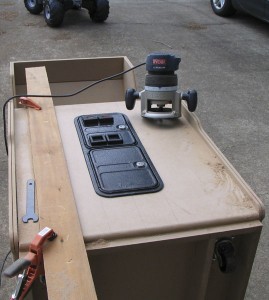
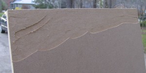
I wanted my CP top to only be 5/8 in. thick sp that when I put the plexi glass on top, the t-molding would cover the seem between the board and the plexi. I can not find any anywhere around here, and believe me I have checked a lot of places. So, seeing that I have been doing quite well with the router, I decided to take a go at routing my CP top down to 5/8.
 |
 |
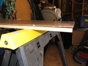 |
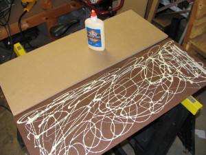
 I think that this picture shows my true realization that routing the 3/4 down to 5/8 is a bad idea. Well perhaps not a bad idea, but it’s not a good idea. So the next idea was to glue a 1/8 in piece of hard board to a 1/2 in piece of MDF. This also is a bad (not a good) idea as the hard board has too much flex and will not lay down flat. I put a half a ton of glue down on the hardboard as it had a texture and I wanted to fill in all the little divots. I brushed it so the glue would be even. I put the MDF board down on the hard board. I noticed very quickly that the edges of the hard board would not lay down. I grabbed every heavy object I could find in the garage. This made the problem worse as now it warped all over the place. Oh well.
Reluctantly I gave in a decided to build my CP top out of 3/4 in MDF. This really hoses my idea of using plexi on top of my CP. I am going to use GGG Electric blue t molding. It would look dumb to have the CP top in black as that seems to be the only color you can get 13/16 t-molding.
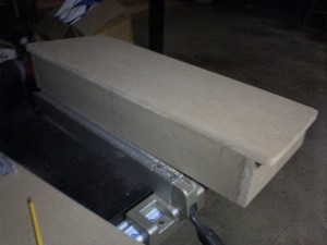
I had another thought (yes it hurt). I could sand a slight bevel from the edge all the way around and still use 3/4 in t-molding. Being that it is under the CP, you would not see it. The picture is not all that great as I had to use my phone camera – Palm 700p. (My wife has the good one and she is in Peru right now.) The top tapers in by 1 inch on each side.
 I have been playing around with how I want to paint on this thing. I want the sides to be consistent with the CP top. Just for grins I took the CP top design and threw it on the sides in a rough mock up in Photoshop just to see if I like it. I LOVE it. I think that I will need to scale a few things differently. I will leave out the side bracket and squish the circle thing so it is horizontally longer and vertically thinner. I think that this thing will rock if I can pull off that paint job. I will need to make a stencil but it is not very difficult as far as shapes n such.


