Oct 182012


I was approached by Dan Thurmon to do a promotional piece for his speaking tours. Dan is a motivational speaker and author. We discussed a number of ideas and set out to make a clean yet interesting presentation. We knew it would be an effects heavy project, so we broke it down to sections.

As we discussed the project I discovered several challenges I needed to solve.

  1. Dan wanted to wanted to juggle and have the balls freeze in mid air, at which point he could walk around them, then have them fall out of the air at any time.
  2. I would have to not only make an animation of juggling, but it would need to transition smoothly from 1 ball up to 5 balls.
  3. Later in the piece he wanted to show the correlation between the topics by drawing a line between the balls.
  4. He wanted the animated balls to come to a complete stop mid talk.
  5. Lastly Dan also wanted a “Danless” version that he was not in that he could use for live situations.

While talking through the process and tossing around ideas, we developed an idea of image frames that would go behind him. I was worried that the image would be somewhat stark if it were just Dan standing on a surface talking to us without some sort of environment. We needed a vehicle that would be clean, visually interesting, and add to the presentation while not becoming a distraction. So I developed a screen ‘system’ that could be driven from the main comp and switch images and move the screens from expression controls.
I needed juggling patterns that would be able to shift to allow additional balls, and a way to work the hands so they would be in the right place at the right time, they would need to open and close at the right time (considering that the frequency would need to shift dynamically based upon the number of balls. More, Dan is a juggler (and I am not) there was also the potential that the pattern I animated would not be correct (in the eyes of a juggler) so the shape of the pattern might need to shift. If I went at this using hand animated cycles, it could have been a terror as if I needed to move one thing, potentially thousands of keyframes would need to be changed, so I decided to animate both the hands and balls with expressions. This led to several other challenges as well…

  • How to add balls to the cycle.
  • Where to add them from as they would essentially be juggled by a bodiless entity.
  • Once a ball joins the cycle, where that ball would sit in the cycle.
  • How to make the balls evenly space when new balls entered.
  • How to keep the balls from overlapping once in the cycle as this would be collision which is not cool if one is juggling.

Once all that was sorted out, then I needed to figure out how to have the hands match up with the balls.
How to have the hand know when it was done with one ball, and it was time to head back to catch the next ball.
Once matched up, then it was a matter of how to have the hand open and close to catch the ball. Being that the hand plate was technically behind the balls, I also needed to solve how to make it seem like the hand actually grabs the ball with fingers actually gripping the ball. I shot Dan tossing a ball over and over. I stabilized this footage. This result was a rotoscoped plate of the hand, and one of just the fingers which was parented to the hand. The expressions ended up being a couple pages long and slowed renders down a little, but my earlier fears were realized when Dan saw the original pattern and asked me to adjust the juggling cycle. Once the cycle was reshaped, all the updates were already done as it was all programmed based upon the shape.

Like most heavy projects, there were many things learned. These types of things are not easy, and can keep one awake at night. But they spark innovation, and we find more efficient ways of doing things. This was a seriously fun project and pushed me in many ways.

Dan did a talk on TED in which he used the ‘Danless’ version. You can find that video here…

 Posted by at 11:13 pm
Feb 042012
 

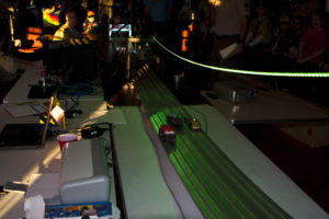
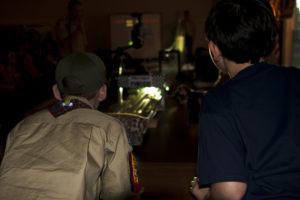
This year, I took the year off of building a car (not by choice). Instead, I took the helm of the whole Pinewood derby. It may surprise you, but the pinewood team (our pack’s leadership) actually spent a considerable amount of time discussing how we could make the whole PWD a smoother experience. This includes everything from the (pre) registration, to the weigh in, to the event it self. When my son was in his first year of Cub Scouts, we just showed up under the delusion that these things just somehow happen. It was really amazing how much time we all spent working on all the little details. We wanted it to be the most massively fun experience possible for the kids. It was an extremely successful and positive night for all.

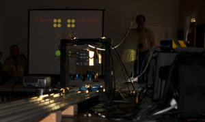
Being techie by nature and profession, I have been adding more and more technology each year. My focus has prior to this year has mainly been on the extra stuff. You know, all the techie stuff not related to the track. This year was really over the top.  We were using 3 projectors sporting racing software, custom ‘Christmas tree’ racing software, and Pinewood TV. We used a full on sound system with speakers all over the place to envelop the spectators and bring them deeper into the event. It was probably overkill, but so worth it.

Last year (2011) we had a fairly serious glitch. The racing software would not communicate with the track and the track stopped… em… tracking. It was an all out frantic search for paper and pencils and trying to decide how to run the race off of paper. In reviewing the issues, this came from an incomplete understanding of how the system worked, and the ins and outs of the race software. Being that I was responsible for the running of this thing, I was going to understand it. Ultimately I found that it all came to a dead halt because of 1 silly little teeny tiny switch. When I meter’d it all out, the switch would not ‘close’. In English, it would not reset the track. If the track is not reset, it (the track brain) stops sending information to the computer. The switch was totally FUBAR. It looked fine. It clicked fine. But when I metered it, there was NO internal connectivity either in the open or closed set of leads. Not sure what happened, but it was done. To compound this when I looked at how it was attached to the track, it was loose (floppy loose), and poorly placed. I decided to re think how it was built. I replaced the switch with a new one, and moved where it was located. I made sure that this was a really solid placement. More, there was a lot of mechanical movement in the area where the switch lives. A lever holds the starting pins in place (The starting pins hold the cars in place at the top of the track). When this is released, several fairly heavy springs on the back pull the starting pins causing them to slam down and under the track thus releasing the cars. There was really no need for so much travel, nor that much umph ( from the springs) to get it there. This was solved with a strip of squishy  foam cut down to fit in the little void behind the starting pin block. This reduced the jarring ‘clack’ down to a gentle ‘doof’ as well as reduced the vibration and stresses placed directly on the switch.

I was feeling some pressure to make sure this thing rocked, so I took some time to learn the racing software inside and out. As with most cottage businesses, the pinewood software started because a den dad had a need and a skill set to match. He started writing the software and it has been growing ever since. While looking through it, I found that it was actually very well written with lots of great features. More, I found out that we could have actually used it during last year’s emergency using a points system mode vs. the time based races which we were using. But one can’t change the past. Oh well.  Trying to be prepared in case the worst happened again (which I was nervously confident that it would not), in addition to the software, we were armed with mass preprinted spreadsheets and pencils.

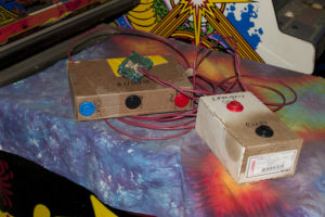
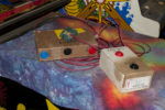
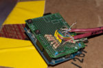
Another upgrade I built last year was the ‘ready’ system to help simple communication between the cogs of the race. When it is loud (crowds of kids and mass excitement), it is hard for the emcee to know if the cars are ready on the track, or if the computer people are ready for the next group to run. So I addressed this by building a ‘ready’ system which would seem natural, but served a very important function. I started by writing a couple of programs in Processing and the  Arduino that would simulate a “Christmas Tree”. Instead of cars crossing a line (telling the computer when it could start) in a real world drag race, I made a button box which sat at the computer position and one start of the track (for the car set up guy). When the computer (pencil and paper) was ready, they would hit their ready button. The same went for the car set up folks. When and only when both groups were set up could the race begin. This was all interfaced through an Arduino into Processing. The races were started by the car set up person. The lights would run the way a real Christmas Tree would run, and when the green lights hit, they would release the cars. This was all accompanied by a ferocious set of sound effects to match. So when they would hit their ready buttons, engine sounds would rev (it was loud and deep enough you could feel it in your chest). The race would start with the Christmas tree lights on the screens blinking down, accompanied by beeps (remember the sounds from the start of the video game Pole Position (if you are old enough to remember) Boop boop Boeeeeeeep!). At the green lights, the sound was of screeching tires and wild engine sounds . When I did the sound design for the audio side of things, I panned the car racing sounds so the sound actually attempted to follow the cars  on the track. A PWD race is really only a couple of seconds long, so I faded the race off into the distance. Lastly, there was an emergency stop button on both button sets. This was for moments where some unforeseen ‘thing’ might pop up.  Either party could press stop and it would kill the sound and reset the display. If the emergency stop was pressed, I used this cheesy VW Bug  ‘meep beep’ noise. In contrast to all this crazy high powered stuff, this rather anemic sounding car horn added a touch of humor. It all worked out very well. The whole thing was put together in a couple of days. It was butt ugly, but it worked wonderfully.

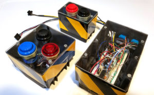
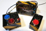
This year I improved on the system quite a lot. I did three things. I built the system to be more rugged, added lighting effects,  and added automated starting of the races so it completely sync’d with the sound. I gutted the cardboard boxes used last year and bought some electrical wall boxes. These were spray painted black (because black looks cooler than blue). Instead of using a standard wall plate for the buttons, I made clear plexiglass covers. I have been talking to the boys about how electronics live all around us and I wanted the kids to be able to look inside the box to see what was making this thing tick. I also reduced the project to a breadboard so they could see how robust a prototype could be (it doesn’t always have to be perfectly printed circuit boards all the time). I found some wonderful reflective yellow and black warning tape at Harbor Freight. This was placed on the boxes which did a killer job of making them look rather menacing. I also added a clear red start button and inserted a wicked bright led so that when the race was set up and ready, it would blink bright red for all to see. The 2 button boxes were connected to the main box via Cat 5, so set up and tear down was super easy.

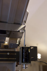
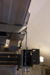
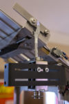
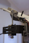
For the automated starting of the races, I bought a solenoid from Sparkfun and built a little mosfet circuit to run it (also housed in the main circuit box). I used one the ears off of a set of server rack rails to mount the solenoid to. Without mutilating the track (which was out of the question) there was no way for the actual solenoid plunger to reach the release lever (which drops the pegs which hold the cars in place). I made a little whachamacallit to attach to the plunger so it could reach up and wrap around the lever. This was cut out of an old metal computer case (my go to material for all my little metal whachamacallits). I did not want to manage multiple voltages (a 12v  system system for lights, and a 24v system for the solenoid). I found that I could under powered the solenoid with 12v. With 12v it had just about enough push that it came pretty close to releasing the start lever as is, but it was not quite enough on it’s own. The solution came through many of the methods used to get PWD cars to run faster. The movement needed to be slicker and smoother. I used a heck of a lot of graphite on all connective surfaces, and minimized any points of friction by sanding a filing my plunger widget completely smooth. These modifications were very effective and the release was flawless. During the PW derby itself the mechanism only failed 3 times during the 100+ races, and 2 of those were due to user set up mistakes. Sorry for the braggin’ moment there, but rarely do projects work that smoothly. I had to take the moment when I could.

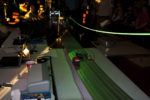
For the lighting, I added a 5 meter strip of RGB LEDs. This was controlled by the same Arduino (actually BoaArduino this year) as the button system. I had to move a couple of pins around from last year as I needed the PWM pins for the LEDs. The track is made out of aluminum which takes light very well. I suspended the strip about a foot above the track. When the ready buttons were pressed, the lights would rev up to match. When the race would start and the lights would blink in synch with the sound which would be in synch with the screen. When the lights went green on the screen, the track would go ape dooky with a strobe of green and bright white. Then when the racing was finished, the lights faded down to red, then down to dim red. If an emergency stop was called, the lights would sit and blink red on and off for about 4 seconds like hazard lights.

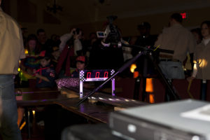
Mentioned above, we also had TV. I brought in a small video switcher (straight cuts only, nothing fancy). I made a 5 minute looped graphic video of racing flames, checkered flags, and a logo. This would play on the screen in between races. There were 2 track cameras. One pointed up at the starting line. This was suspended right over the track on a sort of wood bridge that I made. This was a great shot. You could see the race start and then the cars would fly right at, then under the camera. the camera lens was sitting just 2 inches above the maximum height allowed for cars. (The 2 extra inches was so that I would not get yelled at by some parent who thought that I had somehow had lost their kid the race. While the PWD brings out some of the best qualities in a kid, it brings out some of the worst in some parents (Just sayin’).  The second camera was placed at the end of the track to catch the cars as they went through the finish line. My son actually did the video switching for the night and I must say, he did a great job.

You can not pull off something like this without a great team, and man, all of our Pack 553 leaders stepped up and helped out wherever needed. We started the load in and set up at 10am (the morning of the event), and finished about 5 minutes before it started. While everyone was working hard, no one was rushed. We just did everything we could while we could. After the PWD, it came time to tear down and pack up the car. I will tell you that everything in that room (aside from the track) fit in my Prius. Granted, it probably would have popped if I poked it, but it handled the load.


 Posted by at 6:42 pm
Dec 272011
 

Several people have asked about how I get my PCB boards burned with the results. For a long time I have promised that I would put up a tutorial about how to do it. So, I have an 8 hour drive ahead of me, so here you have it.

Having built a brazillion PCBs on perf board, I wanted something a little more custom. A few years ago, out of ‘necessity’, I decided to learn how to burn my own boards. I routed around online for several days, reading and watching many different methods of how to get the job done. I settled on Eagle Cad for the PCB design and layout. I will not go into how to use Eagle as there are already a number of good tutorials out there. Some of the best I found were this one and this one from Sparkfun. The first couple of boards I designed were slow going. As with all things, it got easier, and I got faster. What I found interesting is how designing on the screen has made clear things would not work on the physical breadboard. When you see the physical connectivity of everything, it just makes more sense.

For the actual boards, I tried a few different methods, but kept getting so-so results. I had seen the Pulsar FX website and read it front to back. For a product web site, there is an amazing amount of “How to” information on their site. I called and spoke with Frank (the owner) about his product. It turns out that he is a fellow tweaker and really cool guy. While I called to talk about his product, I had a great time talking to him about all sorts of geeky things. That is actually what sealed the deal. I bought the laminator a package of the transfer paper and some of the green ‘foil’. You can find his transfer paper on Amazon.

Having done the magazine thing with an iron, you don’t always walk away with good results. The special paper you buy from Pulsar is not a gimmick. If you follow the directions and use the right toner it works very well. I would not have thought that toner would have made that big of difference, but it did. I had some cheap generic toner in my printer and it fell apart. The second I used real, name brand toner, the whole quality game changed. My lines were solid and crisp. It was at that point that I started bringing my trace sizes down. While the product says I can get down to 6 mil (.006 inch), I stayed at a minimum of 10 mil.

Before I start to prepare the toner paper, I get the laminator plugged in and turned on. You want it fully hot when you transfer the toner to the board. You will also want to prep your board here as well. I cut my boards using an old paper cutter. After cutting the boards, I sand the edges using a fine grain sand paper as they tend to be a little sharp. I like the look of rounded edges on PCBs so I sand the edges round as well. This also helps prevent holes when etching (more on this later).

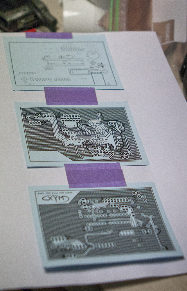
Ok, time to get down to business. While the following is more on how to produce a 2 sided PCB, the same concepts can be used for making single sided boards. I export the PCBs out of Eagle at 300 dpi. There should be 3 or 4 files (Top, Bottom, Front Silk, Bottom Silk). In this case I have 3. I use Photoshop to process my boards. I lay out all 3 files on one page. Eagle sends out a positive image of the board, so I invert the black and white. Any boards using the top must be horizontally flipped so it appears properly when it is etched onto the board. Once everything is set, I make a print to serve as a template for the toner transfer paper.

I cut out 3 pieces of the toner transfer paper (TTP). I cut about a 1/4 inch extra on all sides to leave room for a little play in where the printer prints as well as the possibility of not placing the paper exactly centered. I use a light stick painters tape and tape the TTP over the print on the pre-printed page.  I position the page on the manual feed on the printer and print again. When it comes out, the toner is now printed on the TTP (sorry… duh right?). I carefully pull off the painters tape. It is important that you pull carefully so the paper does not rip, and if it does (which sometimes happens), it does not rip into the print.

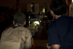
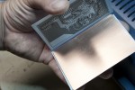
The next step is the moment that I dread the most. This is one of the steps that will either make or break the PCB. It probably does not need to be said, but alignment of the top and the bottom holes of a PCB is critical. I align the top and bottom by facing the prints towards each other. I use a wicked bright 3 watt LED headlamp and shine it through both layers of the TTP. I gently move the top around until I see a good portion of the PCB line up. I then zero in on the right hand side of the paper. Once it is about as close as one can get I squeeze with my right hand and then I move in the left side. Once everything seems to be all lined up, I use a piece of the painters tape and lock the 2 sides together to make a clam shell kind of shape (see the picture below).

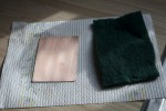
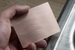
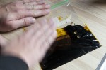
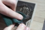
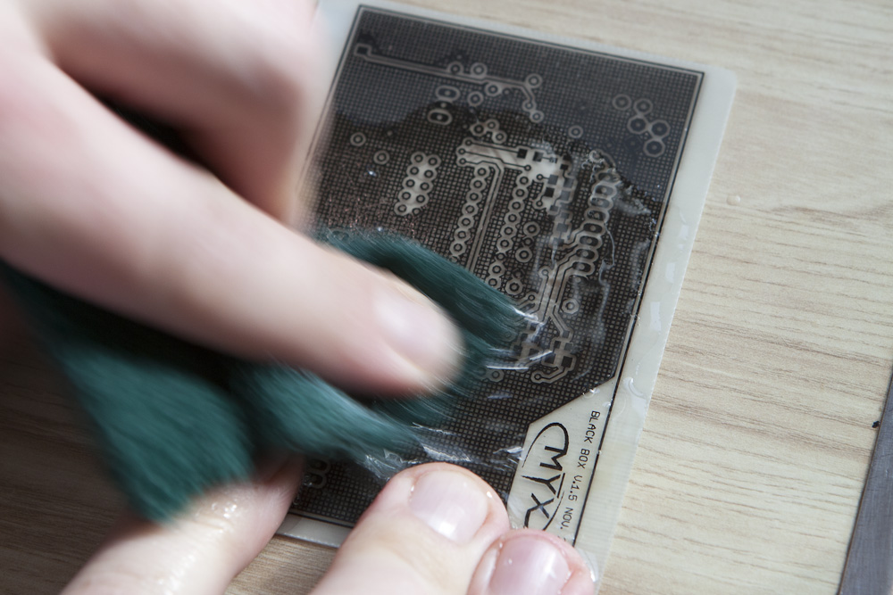
Before I commit the design to the copper, I clean the copper completely with a green scrubby pad. As you scrub it, you can see the copper get shiny. I do not (and recommend that you do not) use soap that uses oil in it’s ingredients for grease break up (like Dawn). You want the board completely free of oils so the toner will stick. At this point I fill a plate with warm water in preparation for the toner’d board.

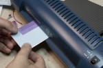
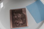
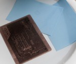
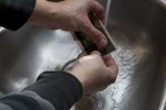
I place the board between the 2 sheets of TTP and make sure that the dimensions of the board are inside the area of the copper. I run it through the laminator 3 or 4 times flipping it over each time. I also move the board to a different position on the rollers so I get the maximum heat transfer per pass. I set the board and paper in the water.This is where the PulsarFX stuff rocks. I usually run my finger over the whole board to make sure it takes the water. I leave it for about 2 minutes, then I check it. The board will freely move when it has released from the paper so there is no question about when it is done. If the board moves it really moves too. It becomes slick on the paper. There is no scrubbing necessary, it just comes off clean.
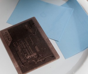
If you are using the green foil, you would add it at this time. The foil fills in any pits or holes that the toner missed (within a certain amount). I do not have a picture of the green foil in this set as I was out of it. This is added to the board by placing it over the toner and running it through the laminator again. Anywhere the toner is, it sticks.
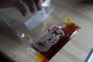
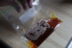
I really like one of the methods of etching the board found on the Pulsar site. The idea is to etch the board in about an ounce of Ferric Chloride inside a plastic ziplock bag. You then repeatedly run your finger over it to agitate the surface. This direct contact results in a really fast burn, which does a couple of things. It insures that no thin traces are over burned, resulting in broken traces. Also, this uses far less FC fluid (i.e. less waste). When I am done etching and cleaning the board, I throw the paper towels into the remaining solution, seal the bag, and toss it in the trash.
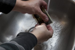
While swiping the surfaces of the board you will see the edges of the copper surface start to fade. Occasionally you will want to look through the board to check the condition of both sides. You want it as clear of any unwanted copper as possible. Again, being that this is such a quick process (3-5 minutes) you have plenty of time to make sure the board is clean. If you still see little remnants of copper, take the time to rework that area of the board in the etchant solution. Once the board is free of excess copper, I pull it out and clean it thoroughly. You do not want any of that fluid on you, or your clothes.

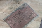
Using the green scrubby pad, scrub the board to get the toner and green foil off the board. You can use acetone to speed the process up a bit and make the job a little easier on your arms. The only drawback to using the acetone is that it melts the toner and the foil which colors the board a bit greenish black. This is not a really a problem, it’s more of a cosmetic thing.
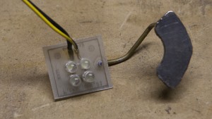
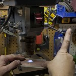
Next up is the drilling of the board. PCBs have little tiny holes and as you may expect, need little tiny drill bits to drill them. I get my bits from Harbor freight as you can occasionally get them on sale. Again, there are many methods to drilling. What I have found to be the easiest is to use my drill press. The problem is your eyes crossing when you are trying to line up the drill bit to the holes. I designed a little magnetic board with 4 white LEDs on it to shine through the hole, and through the board which makes lining up the bit a heck of a lot easier. I keep a 12 v battery on my workbench strictly for this purpose. If the alignment of the top and bottom is the most dreaded part, drilling is probably the second. There are many opportunities to screw up your board during drilling. This is one area where you really want to keep your head straight and stay focused. It is a somewhat long and monotonous process and the holes are small which is a bad combination. I usually keep about a 10 mil of space between the drill tip and the board so the travel to board is at a minimum. While you will want to go fast to get the job done, I have found this to be the key to unsavory holes and broken bits.

 Posted by at 10:56 pm
Jul 142011
 

Yeah, I know massivity is not a real word… just be ok with it.

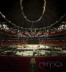
Every 2 years the company I work for holds a rather large convention. I am not talking about a hotel ballroom, nice dinner, and a DJ. I talking about a full on, gigantical, colossal, massivity of a convention. We quite literally took over the Georgia Dome for a little over a week. A massive spectacle with concert sound, lighting, 50,000+ crazy attendees.

My job… shoot it. I shot brazillion pictures and hours of footage which was initially supposed to be edited into a doc. But at the eleventh hour as with most projects, things changed. They now wanted a upbeat rockin’ music video. I had shot everything smooth and slow.  Oh well… But it was still a fun piece though. As far as pictures go, there were too many things to shoot. Everywhere you look there was another something interesting. As I have said in the past, I am a sucker for blinky things and this was the granddaddy of blinky things.

 Posted by at 3:27 am
Feb 222011
 

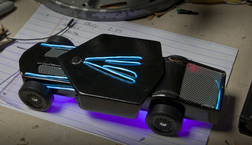
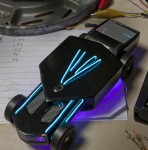
As I have said more than once, I was an 80’s kid. As you know, Tron Legacy came out. While I was a little disappointed in the story, I was totally in love with the art. It was beautifully done with so much attention to the little details. If they paid as much attention to the story, it would have totally rocked… but I digress… I wanted to make this years pinewood derby car in the styling of the new movie.

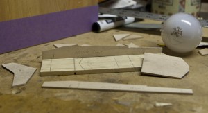
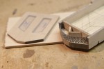
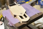
I decided to take a different approach to the building of my car. Instead of starting from a block and working down, I started by sawing the block down to a thin slab and adding to it. Using thin pieces of wood, I carved each piece of the car with the coping saw and / or razor knife. The caliper helped a lot. The wood is soft enough that I could mark the wood easily. I used super glue to keep the weight down. Then I used wood filler to fill in the the cracks between the pieces.

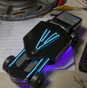
The overall design is something between an F-16 with no wings and a Comaro. The jet intake, rear, hood grill, and the front grill were from an old set of computer speakers. They were of course rear lit as well. The hood was to have plexiglass inbedded in it, but I could not get the fit to not look chunky so the idea was scrapped for the metal.

In the past I have used screws to hold little things like this together. This year I wanted to make it easier to access the guts. I used a little neodymium magnets to hold the top onto the bottom of the car. The only thing I do not like is the bump in the middle of the top piece. There was supposed to be a rear spoiler, but I did not have time to built up the back end to add it.

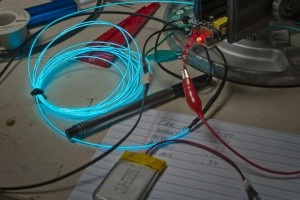
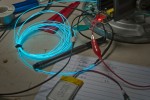
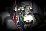
I thought through many different ways to achieve the glowing linage. I bought and experimented with everything from science grade glow in the dark paint, back lit plexi, UV reactive paint with UV LEDs, and eventually settled on EL wire. It is what was used in the movie for the costumes. It was the best look for the size. I had to come up with a way to fit the inverter in the car, be able to turn it on and off, and most importantly, how to power it. I opened the case that the inverter came in and hacked the board so I could move the batteries and switch to the middle of the car. For weight and size reasons I chose to use a small LiPo battery. The last thing I added was 0805 SMD UV LEDs for ground effects and head lights. The effect was very slick. Another nifty (and unintended) effect was that the inverter has a high pitched whine to it. In addition to looking very electric, it also sounded very electric.

Triumph and agony…
Sometimes when you work on things for too long, you loose your mind. This can be a dangerous thing if not to yourself, then to the object being worked on. I spent a lot of time priming and painting the car so it had a near ‘real car’ paint job. I mean, I spent a stupid amount of time painting, sanding, painting, sanding… Then it’s time to put the wheels on. If you have ever built a pinewood derby car, you know that this last step is the time where most cars get damaged, and this build was no different. It was 3 am(ish) and I had to finish the thing as it would be checked in the following day. I put the front wheels on first and they went on without issue. The third wheel went on without issue. On the 4th wheel, as I was tapping the nail in, I heard ‘CRACK’. I put my head down on the workbench and let out a big sigh, pretty much knowing what had just happened. After about 30 seconds or so, I decided to look at what the damage was. The top of the car (in the back) had caved in. This was not something that could be repaired easily, or quickly. I had to get up for work in a few hours and it needed to be turned in right after work. There was no time. I chose to get it at least track worthy. I glued the heck out of the broken area. To add insult to injury, when I picked up the car to look the damage closer and the car fell out of my hands and landed beak down. While it did not break, it added another nice little ding to the killer paint job. There is a lesson in here somewhere… I am not sure what it is yet… but it’s there  ;0) .

 Posted by at 8:09 pm
Dec 122010
 

I have been a fan of weather and storm watching since I was a little kid. It really all started one night when I was in bed in the midst of a wild thunderstorm. I was awake and frightened and thought everyone else was asleep. I heard a noise, and as kids do when they can’t sleep, I went in search of what I was hearing. It was my grandmother. She was standing by the sliding glass window watching out across the lake. I went and stood next to her. I told her that the storm was scaring me. I asked if it was scaring her. She said no. She explained how she loved to watch the storms. We sat there together not really saying a whole lot, just watching the storm. Occasionally we would comment about the lightning or thunder hits. I forgot to be scared. It turned out that I wasn’t. I was amazed.

I have been in many storms since. I have been closer to tornadoes that I would have liked. But all in all, I am still fascinated by the storms. Since I started learning about the mircocontrollers, one of the earliest ideas I had was that I could somehow use one to measure the weather. Early on I did not know how to go about it. But as I have been exploring new areas of technology, as well as learning to build, building, and crafting new things I am starting to understand more and more what can go together. It is somewhat freeing actually.

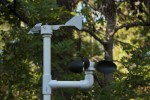
So, weather. Where to begin. Starting with my most basic needs, I need to know how fast the wind is going and from what direction. I decided that I wanted to build an anemometer. There are several folks on the web who have built them, but true to form, I did not see one that sort of suited me. (What can I say, I like making my own stuff). So, I started to play with different ideas. I still had several skateboard wheel bearings from the windmill, but I have found that those will rust when exposed directly to the elements. I could use them, but they would need to be shielded. I wanted to integrate electronics so I could measure the speed. I wanted it to be cheap. I wanted it to be repeatable in case I wanted to do it again.

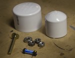
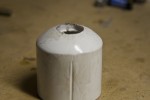
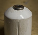
PVC is a great, low cost, experimental building material. It can be cut, shaped, sanded, and painted and put together in countless ways. It’s like Legos for Adults. The way I decided to approach it was to have a cap suspended on top of a smaller cap. The outer cap would need to freely rotate, yet stay connected to the inner cap. An issue I ran into was how to drill a hole in the exact middle of the pvc cap. I have no good scientific answer. I used a ruler and marked lines across the dome. I kept doing this from many angles till one spot showed it’s self as the center. I used a 1/4  2 inch brass bolt. I used brass as this is what they use in toilets and figured it would be outside.

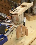
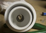
The bolt was put through the end of the cap and nut tightened in place. Before I get too much farther, I should mention that I fit everything together to make sure it all worked then went back and epoxied all the non moving bits. I drilled a hole in the middle of the smaller cap and widened the hole until the ball bearings fit snugly inside. I put the outer cap over the inner cap and added another nut to the inside of the smaller cap to hold the two caps together. The 2 nuts sit directly on the inner rim and not the sleeve of the bearing. Being that the outer rim is firmly attached to the smaller cap, the inner rim spins freely. BTW, something that I did not take into consideration was how to hold the nut as I was tightening it. There is no room for fingers in that small of a space. Needle nose pliers helped out here, but it still was not easy. If you are asking why, remember that the tighter that the nut gets, the further down the large cap gets, which means you have nothing to grip onto after a while because the outer rim spins.
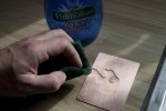
The next issue I needed to figure out was the scoops. I have seen all sorts of ideas ranging from as simple as easter egg cups to folks who have custom machined their own. I wanted something bigger than easter egg shells and far less complex than machining. I could use a makerbot and make whatever shape I wanted, if I had one (Man oh man, I want a makerbot).  One day when trolling the dollar store (a good source for budget makers) I saw a huge display of big plastic spoons. After being an ass and asking how much they cost, I bought 4 of em’. I bought 3 for the build and one to goof up. Not long later, I had the handles removed and ready to attach.
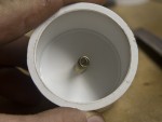
I used super glue at first, but it really did not work well. Epoxy eventually was the right solution. But how does one hold a salad spoon to a round spinable object until it hardens in place? You get comfortable because you are not going any place for a while. With all the goofy angles, there was not a good way to clamp it. Fortunately is was 5 min. epoxy.


For the electrical part of this, I took apart a relay I had in my kit o goodies. If you gently pull on one of the ends of this variety, the glass reeded vial will come out fairly easily. I soldered wires to the leads and covered them in heat shrink to keep the water out. I epoxied the reed to a groove I made on the outside of the inside cap. (clear as mud?) I drilled a hole in the side of the bigger cap just big enough to push a little magnet into. The magnet trips the reed which gives you your pulse for your uC (microcontroller).

The wind vane was dome somewhat similar. But, to make the assembly a little easier (which occurred to me after putting together the anemometer, I bolted in reverse this time. I had the bolt come out of the top of the big cap. Something I did not realize when I started on the arrowish part of the vane was that the 2 sides had to be of equal weight. Who knew. I cut it all out and epoxied it to the cap. It was locked in and when I went to test it, it sort of lazily flopped around, but did not really head into the wind as I had expected. I am writing this some time afterwards and seriously have no idea how I solved this one, but I found that balance was the key. I some metal bits, but it was not enough. I started looking for small, really heavy stuff so I could balance the thing. I remembered the fishing weights we had used for the pinewood derby cars. I cut a slit down the middle of a large weight and epoxied it in place. The vane came to live. While it is ugly as hell, it effortlessly moves about when even the slightest wind is present.

 Posted by at 10:21 am