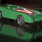
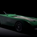
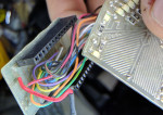
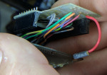
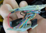
So, it was pinewood derby time for the Cub Scouts again. My son’s pack has a race for the adult kids too. I had been plotting my car since last years races. I wanted to really light the thing up. Last year I had working head and tail lights, but this time I wanted bigger and better. I was just not sure what form it would take. I had considered many options. The most predominant idea was using an accelerometer to change the light settings based on force. The problem was that I wanted the lighting to stay very minimal until race time so that the surprise factor would be maximized.  I was leaning heavily towards the Arduino Pro 3v due to it’s nice and tidy size. After more thought I started heading away from the accelerometer and started thinking about using an XBee to control the Arduino remotely. Then while shopping at Sparkfun one day, I stumbled upon the Funnle IO board and that locked the plan together.
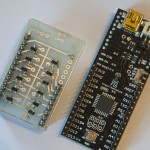
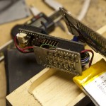
Funnel is an Arduino based board, with the added benefit of having an on board Xbee socket. Plus it is tiny, has a 3.2v line in (for LiPo), and a LiPo charger onboard too.
I ordered the stuff from Sparkfun and started designing the circuits. The mental picture was to make 2 stripes that ran down the sides of the car. These would be able to blink, pulse, fade, and ripple. Then on the 4 corners I wanted to have a very bright strobe light effect that would strobe at about 1 pulse per second. The idea was something like a jet preparing to take off and the taxiing lights. I put together a breadboard mockup. I decided to use the 6 PWM outputs for the stripes. This way I could make them flow however I wanted. I worked on many different ideas for making a slow PWM roll. I finally found that to make the lights really roll along, I needed to have more than one set as the rolling motion is much more pronounced when repeated in a longer strip. The thing started to take form.

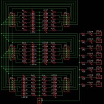
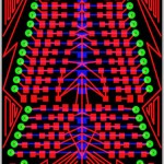
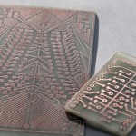
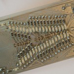
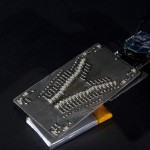
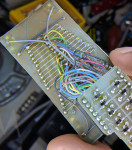
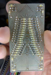
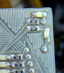
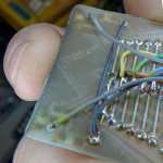
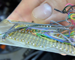
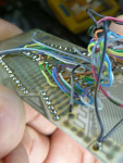
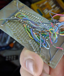
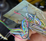
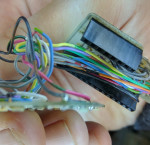
I decided to use 3 sets of 6 LEDs on each side, but instead of running down the sides, they would actually sit on top of the car like some evil menacing engine. I did not want big bumpy 5mm LEDs all over it (which actually might just be cool), so I went with surface mount. All the LEDs and resistors are 1206. 36 LEDs at 20ma each would easily exceed the max draw for the Funnel, so I built a driver board to take the load off of the FIO. The driver board was nothing fancy, just a few small 2222 transistors (sot-23).
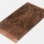
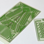
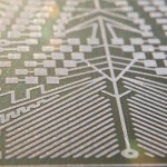
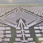
One thing I had a great amount of fun with was designing empty spaces on the board. Once the board was designed, it was quickly clear that though functional, it was hardly cool looking. There was a still ton of blank space, so I decided to decorate the PCB. It was arts n crafts time with Eagle Cad. So, I spent a couple of hours just playing with shapes. By about noon the next day, I had the board etched, and all soldered up, and was ready to start testing. I uploaded the code to the funnel and started to play. I had some problems with one the channels of strip lights. It turned out to be a transistor that was not completely seated on the board. It looked soldered, but when I heated it up and pushed down on it, it just sank. It was a quick fix and it worked great from there on out. I made sure that the xBee was working, but mainly stayed on the ftdi cable during the remainder of programming and testing.
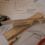
After designing the car, I needed to route out the innards where everything would fit. This was a little easier on paper than it was in wood. Eventually, it started to come together. Making a long story short, I got everything together and it worked great. This was my first real Xbee project. I really liked that I got feedback from the car which was sitting like 60 feet from me. Of course I had to program the Arduino to do so. All I needed to do to trigger an effect was just type a letter into the serial command box in the Arduino IDE. I had about 14 different things I could have it do.
Edit: (News) – My car is on Sparkfun’s Front Page!!! Call it my Andy Warhol 15 seconds. :0)
Edit: (Clarification) – No, I am not employing a “joule thief” circuit in the car. We get to name the cars, and I felt that the name fit. Some folks have asked if this is an “official scout issued” PWD kit. Yes it is, but I used 2 kits. The finished car is legal weight, but just scraping by. The wood weighs almost nothing as it is more or less, a shell. When I weighed it after finally getting all together, it was over by quite a bit. I had to hollow out just about every place that was thick enough to be drilled. I avoided the spaces right around the wheel grooves as I did not want it to bust through during the race. If you look at the front picture on the video, in the reflection in the glass you can see where I had hollowed out the sides. Drilling a car that was already completed was a pucker factor of about 12. I really thought I was going to blow out one of the sides. But even that was not enough, when it raced, it did not have the left screw in place as it pushed the car over the legal weight of 5 oz..
Eagle Boards, Schematics, and Arduino Code


